Click the Analysis ( ) button in the Component Viewer tool bar to select which part characteristics to display (assembly components are not supported):
Different characteristics can be displayed for different Manufacturing Process Groups.
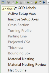
The following display options are available:
-
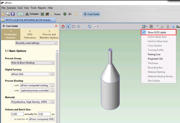
Show GCD Labels: Displays GCD labels for all highlighted GCDs. See Make GCDs Labels Visible.
-
Active Setup Axes: See the setup operations that are currently being used in the machining of the part.
-
Inactive Setup Axes: See the potential setup orientations that are not currently used for the selected machining routing and operations.
-
Cross Section: Shows the cross section of the stock material.
-
Turning Profile:Displays the turning profile (cross-section of the part on a plane passing through the turning axis).
-
Parting Line: Shows the line dividing the top/left side of the mold from the bottom/right side of the mold.
-
Projected CSA: Shows projected cross section area for the part.
-
Thickness: Shows the minimum and maximum thickness of the part walls.
-
Cores: Highlights moving side cores.
-
Bounding Box: The orientation of the bounding box determines the minimum stock size and the orientation of the part within the stock.
-
Material Nesting: Shows how the part’s flat outline is nested within a stock material sheet.
-
Material Nesting Review: show material nesting information in a separate window,
-
Flat Outline: Shows the smallest rectangle that encloses the part before bending.
Make GCDs Labels Visible
The Geometric Cost Drivers (GCDs) pane shows information about the GCDs available for each component and provides tools to edit current GCDs. The GCD labels can be made visible for the highlighted GCDs in the Component Viewer.
To show GCD labels in the Component Viewer:
-
Click the Analysis button,
, in the Component Viewer toolbar.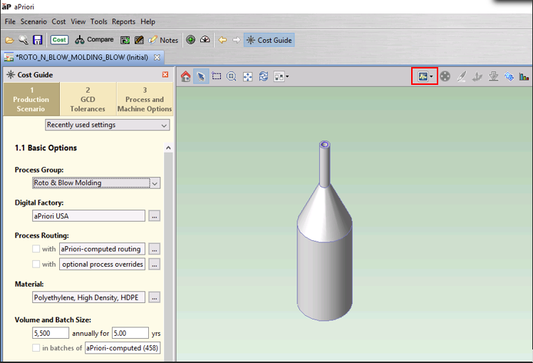
-
Select Show GCD Labels.
-
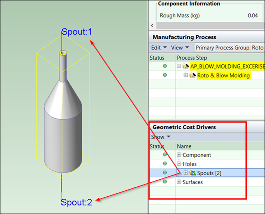
Click a GCD in the Geometric Cost Drivers window. In the Component Viewer, the GCD is highlighted and the GCD label is displayed.
Copy a component image
You can copy the image displayed in the component viewer to the clipboard for pasting into other utilities.
-
Click to select the image in the component viewer.
-
Click Tools > Copy Image from the toolbar.